Full Wave Rectifier Diagram
Rectifier wave circuit tapped diagram center bridge diode capacitor theory filter diodes electronics transformer engineering load power fullwave tap also Rectifier wave circuit precision diagram simple ac dc circuitsstream sourced circuits gr next Rectifier circuit
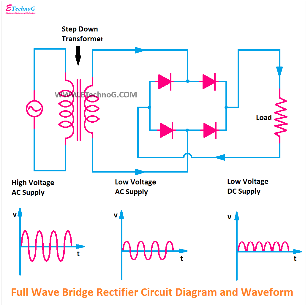
Center Tapped Full Wave Rectifier - its Operation and Wave Diagram
Rectifier center advantages disadvantages electronicscoach Rectifier conventional rectifiers Rectifier circuit diagram
Half wave & full wave rectifier
Full wave rectifierFull wave rectifier circuit working and theory Full-wave rectifierWhat is full wave rectifier ?.
With the help of neat circuit diagram explain the working of half andBuild a full wave rectifier circuit diagram Make three phase full wave rectifier circuit.Rectifier wave circuit theory capacitor working load rl voltage do bridge diagram calculate half output dc its types.

Rectifier diodes thyristors constructed
Full-wave rectifierCenter tapped full wave rectifier Wave rectifier circuit diagram buildEngineering concepts: bridge rectifier versus center tapped rectifier.
Rectifier circuit waveform inputFull wave rectifier circuit explanation Rectifier explain neatWave rectifier circuit principle.

Rectifier wave tapped center circuit diagram operation its contents
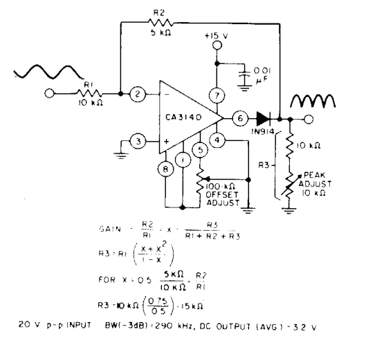
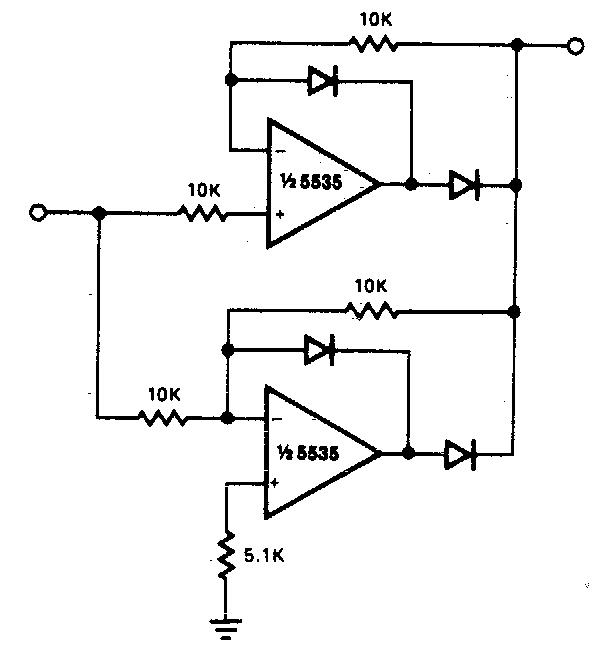
Rectifier wave circuit bridge voltage output working transformer tapped centre across load advantages consistsRectifier explanation Precision full wave rectifier circuit diagram.
.


.jpg)


